I have been continuing on with my clock project. At this point I have the clock itself finished with the exception of the daylight savings time lever. This video shows how I:
Archive for the Contest Entries Category
Clock Project Part 3
Posted in Contest Entries with tags buildlounge.com, clock on December 4, 2011 by jackBuffingtonClock Project Part 2
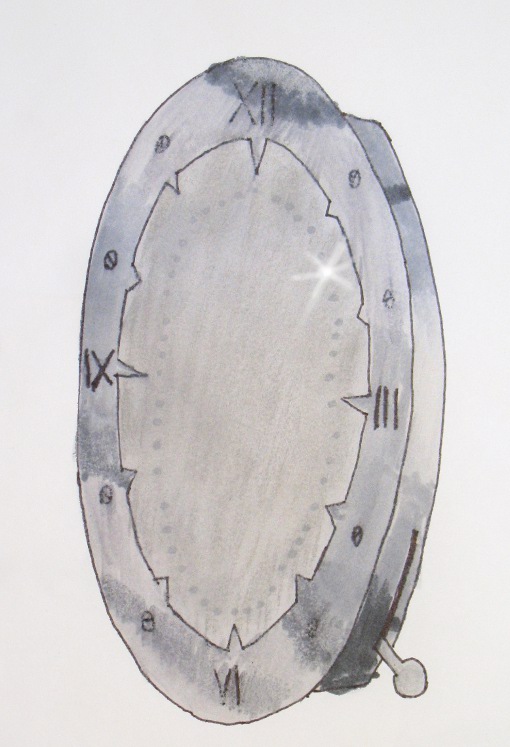
Posted in Contest Entries with tags buildlounge.com, clock on December 1, 2011 by jackBuffingtonIn yesterday’s post I never gave a clear idea of what the finished clock would look like. I intend for it to look like the picture above. The time will be indicated to the nearest 15 minutes or 7.5 minutes if the sunlight happens to be landing on two optical fibers as I intend for it to do if things go right at times like 12:07, 12:22, 12:37 … There is a lever sticking out of the side of the clock. This lever is there to allow you to adjust the clock when daylight savings time rears its ugly head. By rotating the lever you rotate the locations of the optical fibers by one hour.
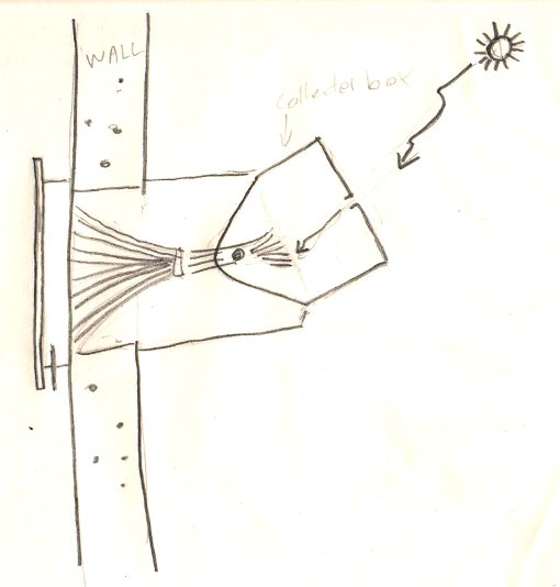
The sketch above is a side view of the solar clock. On the outside of the building there will be a ‘collection box’ that will direct sunlight onto one or two of the optical fibers at a time. The box continues all the way to the wall so that sunlight can’t hit the fibers. I have found that light is collected even if sunlight hits the fiber edge on. The box is adjustable so that as the year progresses, you can aim it so that as the sun goes higher and lower in the sky you will still be able to use the clock. I’m guessing that you will need to do this every week or two to keep things working properly.
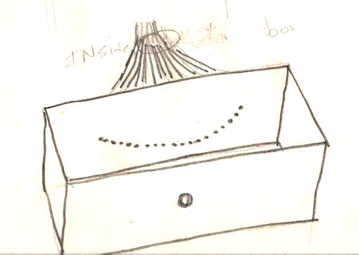
This sketch is of the collection box with its top removed. The optical fibers are in an arc along the back of the box. There is a hole in the front of the box that allows the light to enter. This sketch is somewhat simplified. I have been tracking the sun using a test setup today and it is looking like it might be better to have the material that the optical fibers attach to be in an arc itself because the 15-minute increments are more widely spaced in the beginning of the day than they are at high noon. Ideally, the optical fibers would be placed so that they were in perfect alignment in September or March during the equinox so that you have the greatest accuracy.
Clock project Part 1
Posted in Contest Entries with tags buildlounge.com, clock, router on November 30, 2011 by jackBuffingtonThis is the first of several posts about an entry that I am making for the Buildlounge.com laser cutter contest. The end goal here is to have a clock that has no moving parts and no electronics that still manages to tell the time accurately. This will be something of a modern-day sundial except that it will display the time indoors. The way that it will do this is it will have a box that sits outside. The box will have a hole in it that allows a beam of sunlight to pass through to a series of optical fibers mounted in the back of it. These fibers will run to the back of the clock face and will back light a frosted piece of glass to indicate the time. This first video shows how I cut the face of the clock out of a sheet of aluminum.
Entry for Buildlounge.com’s laser cutter contest.
Posted in Contest Entries, Uncategorized with tags buildlounge, Laser Cutter on November 13, 2011 by jackBuffington
I *REALLY* want a laser cutter but have never had a good enough excuse to buy one so when I found out about the contest going on over at buildounge.com, I decided to enter. The contest requires you to build something that uses light in some manner. Ultimately, I will probably enter two things into the contest. The first one will be a wall sconce that looks like it is made out of regular perforated aluminum but when it is turned on, it will project an image onto an opposing wall. It will do this by varying the diameter of the holes in the aluminum, allowing varying amounts of light to pass through. I have done some tests with different bulbs and different diameters of holes. So far so good. I’ll keep posting updates as I progress.


